A lot of fuss has been and is still being made about the power of use cases and use case diagrams. Use case diagrams though have a limited set of modelling elements, so do not expect too much from them. The narrative part in the use cases however is extremely important, since they form the basis for the later development of your application. They translate your business requirements into functional requirements. So focus on the descriptive part and see the use case diagrams as a mean to:
- List all features of your application
- Define who will interact with the features of the application (users and other systems)
- Promote reusability of features
- Define inheritance between features
You can draw up to 6 different modelling elements on a Use Case Diagram. A use case diagram describes the interaction between the users of the system and the system itself.
Actors
An actor can be a user, a role, a team, a division, a system or any other actor that will use features of the application. Based on the business requirements, you should have a good idea on who will use the system and dependencies with other internal and external systems.
Use
Cases
Based on the business requirements, you can derive
different use cases that will fulfil the actor’s requirements. They are focused
at a certain goal they must
provide to the actors that are using it. Each use case is made up of different scenarios: a normal scenario,
alternative scenarios and exceptions (see later).
Associations
Associations define the interaction between the use
cases and the actors.
Relationships
One can define three kinds of relationships
between use cases:
- Include
- Extend
- Generalisation
Include
This relationship allows reusing certain
use cases which perform common tasks, used by other use cases. When a certain
use case includes another use case, the include use case is called unconditionally, i.e. always. The
include relationship is a way to define reusability in a use case
diagram.
Sometimes the term “uses” is used instead
off “include”.
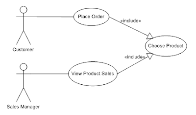
The arrow of the relationship points from
the calling use case to the called use case.
 |
| Figure1: Include |
A customer can place an order and will always need
to choose the product (s)he want to buy. A sales manager can review the sales
of a product by choosing the product for which (s)he wants to see the sales
figures.
Extend
The extend relationship allows an executing
use case to call a certain extension use case under certain conditions.
 |
| Figure2: Extend |
If an error occurs in validating the order
by the validation system, a user within the validation team can correct the order.
The Correct Order extension use case is called under the condition that an
error occurs in the validation of the order.
In both the include and extend relationship,
the calling use case does not know how the included or extended use case works
internally. It is called as a black box.
Generalisation
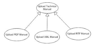
Generalisation allows (like for classes) to
define an inheritance relationship between a general use case and more specific
use cases. The specific use case inherits all features from the general use
case.
 |
| Figure3: Generalisation |
Use Case Description
When describing the use case, the following items
can be addressed. Mandatory items should not be omitted when describing a use
case. As stated, this part is the heart of your functional requirement. Unfortunately
UML does not describe any guidelines for this.
Mandatory Paragraphs
Name
Use a descriptive name. Your use case should always
start with a verb!
Pre-conditions
These are conditions that must be met
before the use case can start. If one of these conditions are not true, the use
case cannot start.
The post-condition of a use case can also
be the pre-condition of another use case. This indicates the logical flow
between the execution of use cases.
Description
In the description, you can write a small
narrative that describes the use case. Don’t forget to include the aim/goal of
the use case, although sometimes this is too obvious to mention.
Remarks
Group here any remarks relating to the use
case:
- TO DO’s
- Information about functionality omitted or reserved for a next phase
- Open Questions
- Technical decisions
Scenarios
This section describes the different
scenarios in the use case. You define the different steps in the use case and
the interaction between actor and the system.
We can distinguish 3 types of scenarios:
This is the happy or normal flow that covers the normal sequence of steps if no error occurs.
Alternative scenarios
The alternative flows or scenarios, sometimes also called extension points, are alternatives of the primary scenario. For each step in the primary scenario, you should ask yourself the question: “Can this step have another outcome? Some of these extension points may also call extension use cases (see Extend). Sometimes you may continue after the alternative flow with a step of the primary scenario.
Exceptions
The alternative flows or scenarios, sometimes also called extension points, are alternatives of the primary scenario. For each step in the primary scenario, you should ask yourself the question: “Can this step have another outcome? Some of these extension points may also call extension use cases (see Extend). Sometimes you may continue after the alternative flow with a step of the primary scenario.
- In complex scenarios, consider using an activity diagram to show all possible scenarios of a use case.
- It is important is to find a way of indicating where in the normal flow alternative flows occur and where exceptions pop-up.
- Remember that exceptions may also occur in alternative flows. Put these exceptions in the alternative flow, not in the exception flow, unless the same exception occurs in both the normal and exception flow.
Example 1
We write explicitly in the step of the primary scenario where the extension or exception occurs.
Primary Scenario
Step
|
Action
|
1
|
User enters search criteria
|
2
|
User presses “Search” button
|
3
|
System displays results of search
Extension
1
Extension
2
Exception
1
|
Extension 1
Step
|
Action
|
1
|
User presses “Cancel” button while
searching
|
2
|
System issues message “Search cancelled”
|
Extension 2
Step
|
Action
|
1
|
System displays “No results found.”
|
Exception 1
Step
|
Action
|
1
|
System displays system error “System
error: no access to query results.”
|
2
|
Post-Condition: search button is
disabled.
|
You can
also group all extension points and exceptions under one paragraph.
Normal Flow
Alternate Flow
·
Extension Point 1
·
Extension Point 2
·
Exception 1
Example 2
In this example we use a different notation:
in the extension we use the number of the step in the primary scenario where
the extension or exception happens.
Primary Scenario
Step
|
Action
|
1
|
User enters search criteria
|
2
|
User presses “Search” button
|
3
|
System displays results of search
|
Extension 1 at step 3
Step
|
Action
|
1
|
User presses “Cancel” button while
searching
|
2
|
System issues message “Search cancelled”
|
Extension 2 at step 3
Step
|
Action
|
1
|
System displays “No results found.”
|
Exception 1 at step 3
Step
|
Action
|
1
|
System displays system error “System
error: no access to query results.”
|
2
|
Post-Condition: search button is
disabled.
|
Example 3
In this example we use the number of the
step in the primary scenario in a slightly different way. The first number
refers to the step of the primary scenario, the second number is a sequential
number within the extensions or exception.
Primary Scenario
Step
|
Action
|
1
|
User enters search criteria
|
2
|
User presses “Search” button
|
3
|
System displays results of search
|
Extensions:
- 3.1:
Step
|
Action
|
1
|
User presses “Cancel” button while
searching
|
2
|
System issues message “Search cancelled”
|
- 3.2:
Step
|
Action
|
1
|
System displays “No results found.”
|
Exceptions:
- 3.1:
Step
|
Action
|
1
|
System displays system error “System
error: no access to query results.”
|
2
|
Post-Condition: search button is
disabled.
|
Post-conditions
The post-conditions describe the situation
or state of the system/application when the normal flow of the use case ends.
Placing them under a separate chapter in your use case increases their
visibility, assuring these post-conditions are met when the normal flow of the
use cases ends.
In some cases, you can also describe the post-conditions for each exception but you should place them in the Scenario part
Optional paragraphs
Number
Numbering can be useful if you stick to a
simple sequential number. If however you put some logic in your numbering (indication
of functional group, main and sub use cases), you will end up in renumbering a
lot of use cases, when new use cases pop-up, which inevitably will happen.
Assumptions
These are conditions the use case assumes
to be true. The use case will never test them.A typical example is that you need to be logged in and passed a security check before you can perform any use case within the application. To repeat this assumption for each use case is of course not needed.
Triggers
A use case is triggered by some event. The
following events are typically used:
- A time event fires of
- A signal is received
- A certain condition is met
- A user initiates a certain action
- A business event occurs
You can also use the first step in your
scenario to define the event that initiates the use case. Up to you to decide
which approach works the best.


No comments:
Post a Comment